

IN-SAR may be space-borne, air-borne, or ground-based. Unlike other remote sensors, IN-SAR provides continuous spatial coverage and is relatively insensitive to the surrounding environment, facilitating long-term overall analysis and prediction. Non-contact sensors mainly include prismatic-free total station, real-aperture radar (RAR), and interferometric radar (IN-SAR). Contact measurement technologies generally troubled by small coverage and risky installation in hazardous areas. The former includes the inclinometer, strain gauge, optical fiber sensor, terrestrial laser scanner (TLS), total station (TS), global positioning system (GPS), and other monitoring systems placed on the surface or embedded in the target body. Current sensors can be divided in contact or non-contact mode categories. A variety of measuring sensors have been used to determine explicit shape variations and regional targets deformation patterns in time and space. The proposed method yields accurate target displacement results via quantitative analysis of GB-SAR interferometry.ĭeformation monitoring and displacement measurement of unstable slopes and buildings are crucial for surface observation and disaster prevention. Finally, we compared the rail sensor measurement and TLS results to optimize coherent scatterer selection and filter the data. The CR displacements can also be extracted via surface reconstruction algorithm. The model is matched with interferograms to produce more intuitive 3D products. We analyze the GB-SAR zero-baseline repeated rail differential interferometry signal model to obtain 2D interferograms of the test site in time series, and then use TLS to obtain a 3D surface model. Three smaller CRs are installed nearby, each with a reflective sticker attached to the CR’s vertex the CRs present as high-amplitude points both in the GB-SAR images and the TLS point cloud to allow for accurate data matching. The rail is equipped with a CR on a sliding platform for mobility. A rail with positioning accuracy of 0.1 mm is deployed to ensure accurate and controllable deformation.

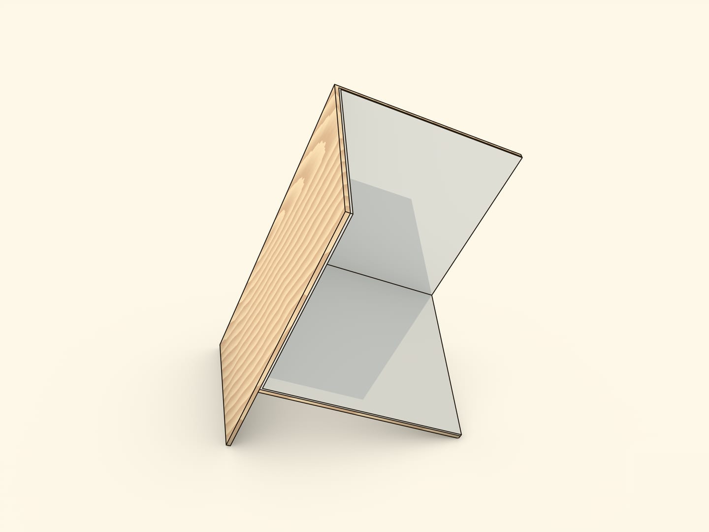
Monopole versions for use at lower frequencies have been built by placing vertical reflecting screens behind a vertical monopole antenna.An integrated sensor system comprised of a terrestrial laser scanner (TLS), corner reflectors (CRs), and high precision linear rail is utilized to validate ground-based synthetic aperture radar (GB-SAR) interferometric micro-displacement measurements.These antennas actually function more like two separate antennas: the corner reflector and driven element serves to provide broad bandwidth gain at the lower end of the UHF band, while the Yagi array is cut to give extra gain at the high end of the band. UHF Yagi television antennas very often use a corner reflector. The single driven element can be replaced by a Yagi array.Several different variations of the antenna are used A parabolic dish this size has no advantage in gain over the corner reflector, so its simplicity of design and construction make it attractive. Corner reflector antennas are particularly suitable in applications where a broadband directional antenna around one to 1 + 1⁄ 2 wavelengths in size is needed. The antenna can be regarded as a form with a gain intermediate between a plane reflective array antenna and a parabolic antenna. Bowtie driven elements are often used for wide bandwidth applications like television antennas. The radiation resistance of the dipole increases with this spacing, so the spacing can be adjusted to match the driven element to the feed line. The spacing (S) of the driven element in front of the point where the reflectors meet is approximately 0.5 λ but is not very critical for 90° antennas the gain doesn't vary more than 1.5 dB for S between 0.25 λ and 0.75 λ. However, angles down to 45° have been used. The gain increases as the angle narrows, but the increase below 90° is minimal, and requires longer reflector screens be used. The angle θ between the sides is most commonly 90°. The spacing of the rods D should not be more than 0.06 (6%) of the wavelength. The flat reflecting surfaces can be metal sheets, but are more often made of wire screen or rod elements parallel to the driven element, to reduce weight and wind loads on the antenna. Construction of a typical corner reflector antenna


 0 kommentar(er)
